After a little careful redirection, movement of my components has now become a part of my project as well as audio and shadow projections. I've been playing a little with movements and changing relationships between the electric motors and the guitar pickups that are generating noise from the produced electromagnetic fields. Here is a quick video of one of them.
Tuesday, October 30, 2007
Sunday, October 28, 2007
Light Controlled Noise in action
Here's a video of the circuit in action. Unfortunately there was sandblasting going on outside our window so the audio isn't what I would like it to be. The operation can be heard though.
Thursday, October 25, 2007

Filling in the blanks
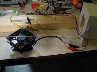
Here are a few images of a couple of my de-monsters that I neglected to post here earlier.
Recording the presence of movement in a space in a paper loop:


Not yet shown is the motion sensor/ AC motor contraption that made the above circuit reactive. Will edit for its addition soon.
Creating reciprocating movement by changing the voltage applied to a fan:

Recording the presence of movement in a space in a paper loop:


Not yet shown is the motion sensor/ AC motor contraption that made the above circuit reactive. Will edit for its addition soon.


Tuesday, October 23, 2007
Light Controlled Noise
My work this past few days has entailed trying to refine the way my pick-ups react to movement. My initial attempts with the motion sensor and the ignition coil provide an auditory cue whenever someone was present, but it was a bit of a Rube Goldberg machine. It required more steps than was necessary to complete the task. Another major failing was that the nature of the noise was exactly the same regardless of the size and speed of what caused the movement.
Addressing these issues I have designed a new setup. It involves an array of photo-transistors attached to an array of Darlington transistors. The photo-transistors are used to trigger the Darlington transistors when they are exposed to light. The Darlington transistors then provide a ground for a DC electric motor- turning it on. The way I am able to differentiate one photo-transistor's input from another is by where in the circuit a ground is applied. The motor is attached to a circuit which is normally open and has a number of resistors (the same amount as the number of photo-transistors minus one) hooked up in series on the ground side of the DC motor. The grounds from each photo/Darlington transistor pairing are applied in different places between these resistors along the circuit. This causes a different amount of resistance to be present between the DC motor and ground depending on which pairing has light, and as such, a different speed is achieved by the motor. This speed difference isn't very obvious visually, but the sound difference from the motor is- especially when the electromagnetic field is picked up by the guitar pickups and amplified.
This development achieved much of what I set out to accomplish, but was still not exactly what i was looking for. The lacking, I felt, was in the way this can be used to respond to movement- especially that of people. When we move around, we don't create light wherever we go- But, we DO create shadows. This caused me to redesign my previous circuit so that when light is received by the photo-transistors power is transferred through to the ground side circuit of the DC motor. This stops the motor when light is present due to the equivalence in voltage on either side of the motor. Once a person moves through the space, they block the light to one or more sensors, causing the transistor pairing to close, and remove the power from the ground side of the DC motor- which in turn allows it to operate. This method requires special attention to dropping of voltages over resistors and the prevention of shorted circuits. The benefits are worth it though as less components are required compared to other solutions. For example, an array of relays could be used to do the same task with a little less hassle, but more cost and unnecessary complexity.
Friday, October 5, 2007
Information sources
In an effort to locate the sources for a lot of the knowledge I've been relying on so far in my experimenting I had to go back to my old text books. Here are a couple of pages from "Physics For Career Advancement" 5th edition by Ewen, Nelson, and Schurter:


Thursday, October 4, 2007
The pick-ups are, well, picking up
With the understanding that the guitar pick-ups are activated by changes in their magnetic field and the creation of a magnetic field around a flowing electrical current it is not surprising that the guitar pickups create noise (when paired with an amp of course) when adjacent to any operating electrical component. This includes wiring. The catch is that having voltage present alone isn't enough, there needs to be a complete circuit that is operating in order to create a response.
Wednesday, October 3, 2007


Electromagnetic Induction Research
Here's a quick look at what I've been finding- This version is lifted directly from the website:
http://www.rare-earth-magnets.com/magnet_university/history_of_magnetism.htm
1820 - Electromagnetism, Current
In 1820, a physicist Hans Christian Oersted, learned that a current flowing through a wire would move a compass needle placed beside it. This showed that an electric current produced a magnetic field.
Andre Marie Ampere, a French mathematician who devoted himself to the study of electricity and magnetism, was the first to explain the electro-dynamic theory. He showed that two parallel wires, carrying current, attracted each other if the currents flowed in the same direction and opposed each other if the currents flowed in opposite directions. He formulated in mathematical terms, the laws that govern the interaction of currents with magnetic fields in a circuit and as a result of this the unit of electric current, the amp, was derived from his name. An electric charge in motion is called electric current. The strength of a current is the amount of charge passing a given point per second, or I = Q/t, where Q coulombs of charge passing in t seconds. The unit for measuring current is the ampere or amp, where 1 amp = 1 coulomb/sec. Because it is the source of magnetism as well, current is the link between electricity and magnetism.
1830 - Inductance
In 1830, Joseph Henry (1797-1878), discovered that a change in magnetism can make currents flow, but he failed to publish this. In 1832 he described self-inductance - the basic property of inductor. In recognition of his work, inductance is measured in henries. The stage was then set for the encompassing electromagnetic theory of James Clerk Maxwell. The variation of actual currents is enormous. A modern electrometer can detect currents as low as 1/100,000,000,000,000,000 amp, which is a mere 63 electrons per second. The current in a nerve impulse is approximately 1/100,000 amp; a 100-watt light bulb carries 1 amp; a lightning bolt peaks at about 20,000 amps; and a 1,200-megawatt nuclear power plant can deliver 10,000,000 amps at 115 V.
1855 - Electromagnetic Induction
Michael Faraday (1791-1867) an Englishman, made one of the most significant discoveries in the history of electricity: Electromagnetic induction. His pioneering work dealt with how electric currents work. Many inventions would come from his experiments, but they would come fifty to one hundred years later. Failures never discouraged Faraday. He would say; "the failures are just as important as the successes." He felt failures also teach. The farad, the unit of capacitance is named in the honor of Michael Faraday.
Faraday was greatly interested in the invention of the electromagnet, but his brilliant mind took earlier experiments still further. If electricity could produce magnetism, why couldn't magnetism produce electricity. In 1831, Faraday found the solution. Electricity could be produced through magnetism by motion. He discovered that when a magnet was moved inside a coil of copper wire, a tiny electric current flows through the wire. H.C. Oersted, in 1820, demonstrated that electric currents produce a magnetic field. Faraday noted this and in 1821, he experimented on the theory that, if electric currents in a wire can produce magnetic fields, then magnetic fields should produce electricity. By 1831, he was able to prove this and through his experiment, was able to explain, that these magnetic fields were lines of force. These lines of force would cause a current to flow in a coil of wire, when the coil is rotated between the poles of a magnet. This action then shows that the coils of wire being cut by lines of magnetic force, in some strange way, produces electricity. These experiments, convincingly demonstrated the discovery of electromagnetic induction in the production of electric current, by a change in magnetic intensity.
1880-
James Maxwell (1831-1879) a Scottish mathematician translated Faraday's theories into mathematical expressions. Maxwell was one of the finest mathematicians in history. A maxwell is the electromagnetic unit of magnetic flux, named in his honor. Today he is widely regarded as secondary only to Isaac Newton and Albert Einstein in the world of science.
Subscribe to:
Posts (Atom)
